 |
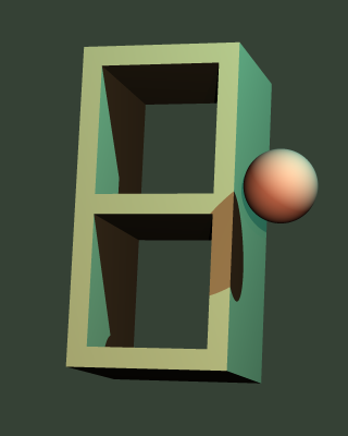
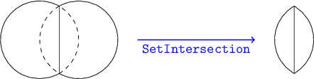
Figure 14.1: The set intersection of two overlapping spheres. |
Although it is possible to create a custom class for every desired shape one might imagine, it does involve a fair amount of mathematical and programming effort each time. Some shapes might be a combination of shapes we have already implemented, or a portion of an existing shape. For cases like these, it is often possible to avoid a lot of effort by using some C++ classes in imager.h that allow us to combine other shapes to create new ones. These classes are called set operators. We can think of any solid object as a set of points in space. For example, a sphere is the set of all points whose distance from its center is less than or equal to its radius. The set operator classes are:
This is the simplest set operator to understand. Given two SolidObject instances, the SetUnion creates a single object that includes both of them. For example, if you had code that created a sphere and a cube, the union of the sphere and the cube would act as a single object comprised of both objects together. The sphere and cube might overlap or they might have some empty space between them. But in either case, you could rotate or translate the set union, and the sphere and cube would both respond to each rotation or translation. But class SetUnion is more than a mere container; its power increases when used in combination with other set operators, as we will see later.
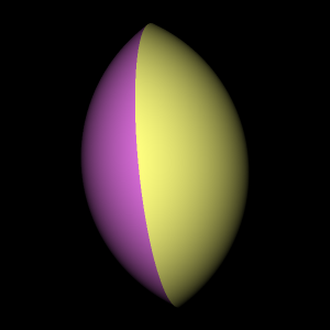
Like SetUnion, class SetIntersection operates on two solid objects to produce a new solid object. However, instead of including all points that are in either of the solid objects like SetUnion does, SetIntersection includes only the points that are in both of the objects. Using SetIntersection makes sense only when the two objects overlap to some extent. For example, let's take a look at what happens when we create two overlapping spheres and feed them to SetIntersection. See Figure 14.1.
| |
|
The resulting solid is not a sphere, but a sort of lens shape with a sharp circular edge. The function SetIntersectionTest in main.cpp shows exactly how to implement this overlapping sphere intersection example. If you have run the unit tests, it has already created the image file intersection.png, reproduced in Figure 14.2.
| |
|
It may seem odd that the left and right parts of the lens are shaded differently. If you look at the image file intersection.png you will see that the left part of the lens is purple and the right part is yellow. Let's take a closer look in main.cpp at the source code that creates the two spheres and their set intersection (the function SetIntersectionTest), to understand the coloring oddity:
    // Display the intersection of two overlapping spheres.
    const double radius = 1.0;

    Sphere* sphere1 = new Sphere(
        Vector(-0.5, 0.0, 0.0),
        radius,
        Color(1.0, 1.0, 0.5)
    );

    Sphere* sphere2 = new Sphere(
        Vector(+0.5, 0.0, 0.0),
        radius,
        Color(1.0, 0.5, 1.0)
    );

    SetIntersection *isect = new SetIntersection(
        Vector(0.0, 0.0, 0.0),
        sphere1,
        sphere2
    );
The color parameter used to create sphere1, Color(1.0, 1.0, 0.5), has more red and green, but less blue, resulting in an overall yellowish tone. On the other hand, sphere2's color is more red and blue than yellow, giving it a purplish tone. The rule for a set intersection's surface color is that when a camera ray intersects with one of the two solids, the intersection point takes on that solid's surface color if the same point is contained by the other solid. (If not contained by the second solid, the point is ignored because the two solids do not overlap at that location.) The rationale for this rule is that only the surfaces of a solid (not its insides) have a color, and each class derived from SolidObject is free to assign colors to every point on its surface as it sees fit— there is no requirement that a solid's surface be of a uniform color. If you, as an artist/programmer, wish to create a set intersection object with a consistent color across its entire surface, you will need to give the SetIntersection constructor two objects of the same color.
At this time we need to rivisit more thoroughly a function that was mentioned earlier, but only in passing: the virtual method SolidObject::Contains. Take a look in imager.h at the class SolidObject declaration. You will see the following within it:
    // Returns true if the given point is inside this solid object.
    // This is a default implementation that counts intersections
    // that enter or exit the solid in a given direction from the point.
    // Derived classes can often implement a more efficient algorithm
    // to override this default algorithm.
    virtual bool Contains(const Vector& point) const;
This member function is implemented in the source file solid.cpp. This default implementation will work for any solid that is fully enclosed, meaning that its surfaces completely seal off an interior volume of space without leaving any cracks or gaps. By default, a SolidObject is assumed to be fully enclosed, but any derived class can override this behavior by passing false for the _isFullyEnclosed parameter of the SolidObject constructor. In this case, SolidObject::Contains will immediately return false every time it is called. Such an object will not be able to participate in set intersection operations (or refraction for that matter).
However, if the solid object is created claiming to be fully enclosed via passing the default value of the _isFullyEnclosed parameter (true), then SolidObject::Contains will determine whether a point is contained by the solid using a boundary-crossing algorithm: the function draws a ray from the point in question and counts how many times the ray enters or leaves the solid. It does this using the same AppendAllIntersections function used by the ray tracer to follow rays of light through the scene. If a point is inside a fully-enclosed solid, no matter what the shape of that solid is, a ray will exit the solid one more time than it enters the solid. For example, starting at a point inside a sphere, the ray would intersect with the sphere one time, resulting in a single exit point and no entry points. If a point is outside the solid, the number of entry and exit points is the same, no matter which direction you draw the ray.
This algorithm works fine, but it is somewhat complicated and not ideal in its run-time efficiency. Therefore, wherever possible, it is a good idea to override Contains on any new classes you derive from SolidObject. If your class derives from SolidObject_Reorientable, you should override ObjectSpace_Contains instead, which does the same thing as Contains, only it is passed a point that has already been converted from camera space coordinates to object space coordinates. For example, class Sphere implements Contains, while class Torus implements ObjectSpace_Contains. Of all the solid object classes I wrote for this book, only TriangleMesh uses the default implementation of Contains; in every other case, it was easy to create a much more efficient replacement.
Whenever SetIntersection finds a ray intersecting with one of its two inner solids, it calls the Contains method on the other solid to determine whether that point is part of the common volume occupied by both objects (Contains returns true) or whether the point should be ignored (Contains returns false).
Incidentally, you may remember from an earlier chapter that the Contains method is also called by the refraction code to determine the refractive index of an arbitrary point in space: the scene iterates through the solid objects inside it, asking each of them if it contains the point. If a point is claimed by a solid, that solid's refractive index is used as the refractive index of that point in space.
Unlike SetUnion and SetIntersection, which operate on two solids, class SetComplement operates on a single solid. The complement of a solid object is the set of points that are not inside that object. If a point is contained by a solid, it is not contained by the set's complement, and if a point is not contained by a solid, it is contained by the complement. As an example of this idea, imagine an instance of class Sphere. Ray-tracing an image of it results in what looks like a ball of solid matter floating in an infinite void. The complement of this sphere would be an infinite expanse of solid matter in all directions, with a spherical hole inside it. This does not sound very useful— the camera immersed in an infinite expanse of opaque substance will not be able to see anything! The truth is, SetComplement used by itself does not make much sense, but it is very useful when combined with the other set operators, as we shall soon see.
As you might expect, when SetComplement::Contains is called, it calls the Contains method on its inner object and returns the opposite boolean value. Returning to the same example, if the inner object is a sphere, and Sphere::Contains reports that a given point is inside the sphere by returning true, SetComplement::Contains returns false, indicating that the point resides within the spherical bubble, i.e., outside the solid matter that comprises the complement.
Interestingly, SetComplement::AppendAllIntersections simply calls the AppendAllIntersections method on its inner object, because an object's surfaces are in exactly the same places as those of the object's complement. However, it must modify the surface normal unit vector for each Intersection struct reported by the inner object, because the complement operation effectively turns the inner object inside-out. A sphere with normal vectors pointing outward from the sphere's solid matter into empty space becomes an empty bubble with normal vectors pointing inward, again away from the infinite expanse of solid matter and into the empty space within the bubble. These implementation details are crucial to make class SetComplement behave correctly when combined with the other set operators.
Like SetUnion and SetIntersection, SetDifference operates on a pair of inner objects. Unlike those other binary set operators, SetDifference means different things depending on the order the two inner objects are passed into its constructor. We will call the first inner object the left object and the second object the right object. The SetDifference creates a solid object that contains all the points of the left object except those that belong to the right object. Figuratively speaking, the left object is like a piece of stone, and the right object (to the extent that it overlaps in space with the left object) determines which parts of the left object should be carved away.
Like SetIntersection, SetDifference makes sense only when the right object overlaps with the left object at least a little bit. If the two inner objects of a SetIntersection nowhere overlap, the result is no visible object at all— just complete emptiness. Non-overlapping inner objects fed to SetDifference result in an object that looks just like the left object. In both cases, the set operator adds no value, and just slows down execution of the ray tracer with useless work. The algorithm will still work correctly in a mathematical sense, but with no practical benefit.
SetDifference is implemented using SetIntersection and SetComplement. The difference of the left object L and the right object R is defined as the intersection of L and the complement of R:
difference(L, R) = intersection(L, complement(R))
We can read this as saying that a point is in the set difference only if it is inside the left object but not inside the right object.
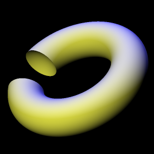
The ray tracer unit test exercises the SetDifference operator with the function SetDifferenceTest, located in main.cpp. This test function creates a SetDifference object having a torus as its left object and a sphere as its right object. The resulting image looks like a donut with a spherical bite taken out of it, hence the image file's name, donutbite.png. See Figure 14.3.
| |
|
Set operators would be quite limited if their operands could only be simple shapes. Fortunately for our creative freedom, the classes SetUnion, SetIntersection, SetComplement, and SetDifference derive from SolidObject, so we can pass set operators as constructor arguments to other set operators. One use of this technique is to circumvent the apparent limitation of SetUnion, SetIntersection, or SetDifference operating on only two objects. Suppose we want to create the set intersection of three objects A, B, and C. Because the SetIntersection constructor allows only two SolidObject instances to be passed as arguments, we cannot use it to directly represent intersection(A,B,C). However, we can create an object intersection(A,B), and pass that new object as the left argument, along with C as the right argument, to create another intersection object. Conceptually, this looks like the following pseudo-code:
intersection(intersection(A, B), C)
In actual C++ code, we must also pass the location in space that serves as the center of the object formed by the set operator. The center is represented as a vector, and all rotations of the set operator object will cause it to pivot about that center point. Also, all inner objects must be created using dynamic allocation via operator new, or a crash will occur in the set operator's destructor when it attempts to use operator delete to destroy its inner objects. So with these details in mind, here is a more realistic listing of a set intersection applied to three objects A, B, and C:
    SolidObject* A = new /*Whatever*/;
    SolidObject* B = new /*Whatever*/;
    SolidObject* C = new /*Whatever*/;
    SolidObject* isect = new SetIntersection(
        A->Center(),
        new SetIntersection(A->Center(), A, B),
        C
    );
    scene.AddSolidObject(isect);
This listing shows A's center point used as the center for the intersection object's center, but any other point is allowed; you are free to choose any point in space for the intersection object to revolve about. Also, if you use the Move member function to move the intersection object to another location, the existing center point will be moved to that new location, and all inner objects (A, B, and C in this case) will be shifted by the same amount in the $x$, $y$, and $z$ directions. For example, if A->Center() and isect->Center() are both $(1,2,3)$, B->Center() is $(5,10,4)$, and C->Center() is $(0,6,2)$, and we do isect->Move(1,1,1), then all three objects will by moved by the amount $(1,1,1)-(1,2,3)=(0,-1,-2)$. So A and isect will both end up centered at $(5,9,2)$ and C will be centered at $(0,5,0)$.
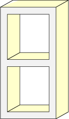
Now we will explore how to use set operators to create an image of a concrete cinder block as shown in Figure 14.4.
| |
|
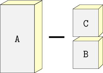
In Figure 14.5 we see that the concrete block shape consists of the large cuboid shown on the left with two smaller cuboids on the right subtracted from it.
| |
|
The header file block.h shows how to create the concrete block shape with a concise class declaration. The class ConcreteBlock derives from SetDifference. It creates a large cuboid as the SetDifference's left object, and a SetUnion of the two smaller cuboids as the SetDifference's right object. Referring to th labels A, B, and C in the previous diagram, we have the ConcreteBlock defined conceptually as
block = difference(A, union(B, C))
The ray tracer unit test calls the function BlockTest in main.cpp, and that function creates an image of a ConcreteBlock with a Sphere casting a shadow onto it. The output file is block.png, which is reproduced in Figure 14.6.
| |
|