 |
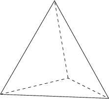
Figure 12.1: A tetrahedron has four equilateral triangles as faces. |
The C++ class TriangleMesh derives from SolidObject. It represents a solid object whose surfaces are all triangles. A simple example of such a solid is the four-sided regular polyhedron called the tetrahedron (see Figure 12.1).
| |
|
Creating a visible solid like the tetrahedron proceeds with the calling code following steps like these:
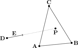
I will explain here how the math works for finding an intersection of a ray with a single triangle. TriangleMesh applies the same math to every triangle it contains when its AppendAllIntersections method is called. Each valid intersection gets appeneded to the output parameter intersectionList. Given a triangle whose vertices are $\mathbf{A}$, $\mathbf{B}$, and $\mathbf{C}$, we wish to know whether a ray starting at vantage point $\mathbf{D}$ and pointing in direction $\mathbf{E}$ passes through the plane of triangle $\mathbf{A}\mathbf{B}\mathbf{C}$, and if so, where the intersection point $\mathbf{P}$ is. (See Figure 12.2.) We will determine in the next section whether $\mathbf{P}$ is actually inside the triangle or not, but first things first.
| |
|
As usual, we start with the parametric ray equation
\begin{align*} \mathbf{P} & = \mathbf{D} + u \mathbf{E} \\ (P_x, P_y, P_z) & = (D_x + u E_x, D_y + u E_y, D_z + u E_z) \end{align*}
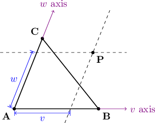
Now we have to write parametric equations for every point $\mathbf{P}$ on the plane of the triangle $\mathbf{A}\mathbf{B}\mathbf{C}$. Because any plane is a two-dimensional surface, we will need a parametric equation with two unknowns as parameters. Let's call the new parameters $v$ and $w$. How do we construct a parametric equation that allows us to sweep through every point on the plane passing through the points $\mathbf{A}$, $\mathbf{B}$, and $\mathbf{C}$, just by varying the values of the scalar parameters $v$ and $w$? There are many possibilities, but here is the approach I took. I pretend that an axis passing through $\mathbf{A}$ and $\mathbf{B}$ is the "$v$ axis" and an axis passing through $\mathbf{A}$ and $\mathbf{C}$ is the "$w$ axis". Then each point on the plane has a location with a $v$ coordinate and a $w$ coordinate. At first it may seem wrong to have a coordinate system where the two axes, $v$ and $w$, are not required to be perpendicular. But if we are careful to make no assumptions that require perpendicular axes, things will work out just fine. Figure 12.3 shows how this coordinate system can specify an arbitrary point on the plane that passes through three points $\mathbf{A}$, $\mathbf{B}$, and $\mathbf{C}$.
| |
|
We extend a line starting at $\mathbf{A}$ and proceeding through $\mathbf{B}$. This line extends infinitely along that direction, and becomes our $v$ axis. Likewise, the $w$ axis starts at $\mathbf{A}$ and extends through $\mathbf{C}$ and off to infinity. For any point $\mathbf{P}$ on the same plane as $\mathbf{A}\mathbf{B}\mathbf{C}$, we can draw lines through $\mathbf{P}$ that are parallel to the $v$ and $w$ axes, as indicated by the dashed lines in Figure 12.3. The line passing through $\mathbf{P}$ parallel to the $v$ axis will pass through the $w$ axis somewhere, and the one parallel to the $w$ axis will pass through the $v$ axis at another location. We can think of these locations along the $v$ and $w$ axes as "shadows" of the point $\mathbf{P}$ falling onto them. I will define the value $v$ as the $v$ component of $\mathbf{P}$ ($\mathbf{P}$'s shadow on the $v$ axis) and $w$ as the $w$ component of $\mathbf{P}$ ($\mathbf{P}$'s shadow on the $w$ axis). Furthermore, $v$ can be thought of as the fraction of the distance along the line segment $\mathbf{A}\mathbf{B}$ that the shadow lies, such that $\mathbf{A}$ is at $v=0$ and $\mathbf{B}$ is at $v=1$. For example, if the shadow of $\mathbf{P}$ lies one fourth of the distance from $\mathbf{A}$ to $\mathbf{B}$, we say that $v=0.25$. Negative numbers work fine also: if the shadow of $\mathbf{P}$ on the $v$ axis is the same distance from $\mathbf{A}$ as $\mathbf{B}$ is, but is in the opposite direction as $\mathbf{B}$, we say that $v=-1$. If $\mathbf{P}$'s shadow on the $v$ axis is in the same direction as $\mathbf{B}$ from $\mathbf{A}$, but is twice as far away, we say that $v=2$. So $v$ may have any value from $-\infty$ to $+\infty$, depending on where $\mathbf{P}$ is on the infinite plane passing through the triangle $\mathbf{A}\mathbf{B}\mathbf{C}$. Analogously, $w$ is defined as the fraction along the line segment $\mathbf{A}\mathbf{C}$ that the shadow of $\mathbf{P}$ measures along the $w$ axis.
In vector notation, we can think of $v$ and $w$ as scalars that we multiply with the vectors from $\mathbf{A}$ to $\mathbf{B}$ and from $\mathbf{A}$ to $\mathbf{C}$, respectively, to get displacement vectors from $\mathbf{A}$ along those two axes. Any point $\mathbf{P}$ is the sum of these two displacement vectors along the two axes, plus the starting point $\mathbf{A}$:
\[ \mathbf{P} = \mathbf{A} + v(\mathbf{B}-\mathbf{A}) + w(\mathbf{C}-\mathbf{A}) \]
Let's try some examples to test whether this equation makes sense. If we choose $\mathbf{P}$ to be at the same location as $\mathbf{B}$, we expect $v$, the fraction from $\mathbf{A}$ to $\mathbf{B}$ along the $v$ axis, to be 1. Likewise, we expect $w$ to be 0, since we don't travel at all along the $w$ axis. Plugging $v=1$, $w=0$ into the equation, we find:
\begin{align*} & \mathbf{P} = \mathbf{A} + 1(\mathbf{B}-\mathbf{A}) + 0(\mathbf{C}-\mathbf{A}) \\ & \mathbf{P} = \mathbf{A} + (\mathbf{B}-\mathbf{A}) \\ & \mathbf{P} = \mathbf{B} \end{align*}
So that case works. As another example, to select $\mathbf{P}=\mathbf{C}$, we can test with $v=0$, $w=1$:
\begin{align*} & \mathbf{P} = \mathbf{A} + 0(\mathbf{B} - \mathbf{A}) + 1(\mathbf{C} - \mathbf{A}) \\ & \mathbf{P} = \mathbf{A} + (\mathbf{C} - \mathbf{A}) \\ & \mathbf{P} = \mathbf{C} \end{align*}
That works too. And if both $v$ and $w$ are 0, we have not moved from $\mathbf{A}$ at all:
\begin{align*} & \mathbf{P} = \mathbf{A} + 0(\mathbf{B} - \mathbf{A}) + 0(\mathbf{C} - \mathbf{A}) \\ & \mathbf{P} = \mathbf{A} \end{align*}
The parametric ray equation
\begin{align*} & \mathbf{P} = \mathbf{D} + u \mathbf{E} \end{align*}
and the parametric plane equation
\begin{align*} & \mathbf{P} = \mathbf{A} + v(\mathbf{B}-\mathbf{A}) + w(\mathbf{C}-\mathbf{A}) \end{align*}
describe the set of all points on a ray and the set of all points on a plane, respectively. If the ray intersects with the plane, both equations must refer to the same point $\mathbf{P}$ where the ray meets the plane, so we can set the right-hand sides of the equations equal to each other:
\[ \mathbf{D} + u \mathbf{E} = \mathbf{A} + v(\mathbf{B} - \mathbf{A}) + w(\mathbf{C} - \mathbf{A}) \]
At first, this seems insoluble, because there are three unknowns $(u, v, w)$ but only 1 equation. But this equation is a vector equation in three spatial dimensions, so we can rewrite it:
\begin{align*} (D_x + u E_x, D_y + u E_y, D_z + u E_z) & = (A_x, B_x, C_x) \\ & + v(B_x - A_x, B_y - A_y, B_z - A_z) \\ & + w(C_x - A_x, C_y - A_y, C_z - A_z) \end{align*}
This becomes three linear scalar equations in three unknowns:
\[ \begin{cases} & D_x + u E_x = A_x + v(B_x - A_x) + w(C_x - A_x) \\ & D_y + u E_y = A_y + v(B_y - A_y) + w(C_y - A_y) \\ & D_z + u E_z = A_z + v(B_z - A_z) + w(C_z - A_z) \end{cases} \]
We can rearrange the terms to arrive at the usual form for systems of linear equations, with each unknown term having a known coefficient on the left and the unknown variable on the right, and a constant term, all adding up to zero:
\[ \begin{cases} & 0 = E_x u + (A_x - B_x)v + (A_x - C_x)w + (D_x - A_x) \\ & 0 = E_y u + (A_y - B_y)v + (A_y - C_y)w + (D_y - A_y) \\ & 0 = E_z u + (A_z - B_z)v + (A_z - C_z)w + (D_z - A_z) \end{cases} \]
I will not go into the details of solving this system of equations, because this is a topic in algebra that is covered well by many other authors.
If you look for class TriangleMesh in imager.h, you will see that AttemptPlaneIntersection is one of its member functions. It tries to solve the above system of equations using the utility method SolveLinearEquations that is declared in algebra.h and implemented in algebra.cpp.
I say it tries to solve the system, because there are special cases where the solver cannot find a solution because it must avoid dividing by zero. This can happen, for example, if the ray is parallel to either $\mathbf{B}-\mathbf{A}$ or $\mathbf{C}-\mathbf{A}$. In triangle.cpp, you will see that TriangleMesh::AppendAllIntersections will try the points of a triangle in up to three different orders, $(\mathbf{A},\mathbf{B},\mathbf{C})$, $(\mathbf{B},\mathbf{C},\mathbf{A})$, and $(\mathbf{C},\mathbf{A},\mathbf{B})$, because sometimes one or two of the orders can fail but another succeeds.
If we find a triplet of values $u$, $v$, $w$ that solve the system of equations, it just means that the point $\mathbf{P} = \mathbf{D} + u \mathbf{E}$ on the ray is also on the plane passing through the triangle $\mathbf{A}\mathbf{B}\mathbf{C}$. As always, we have to check for $u > 0$ to determine whether $\mathbf{P}$ lies in the intended direction $\mathbf{E}$ from the vantage point $\mathbf{D}$. But we also must validate that $v$ and $w$ refer to a point inside the triangle $\mathbf{A}\mathbf{B}\mathbf{C}$ itself, not just some point on the infinite plane passing through that triangle.
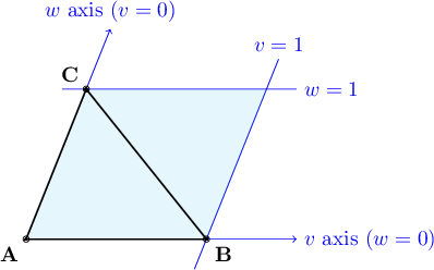
Based on our earlier discussion of what the parameters $v$ and $w$ mean, we know that both must be in the range 0 to 1, but that is not sufficient for ensuring that the point is inside the triangle. Let's take a look at the region of the plane covered by constraining $0 \le v \le 1$ and $0 \le w \le 1$, shown in Figure 12.4.
| |
|
The region of the plane between the horizontal lines $w=0$ and $w=1$ is an infinitely wide horizontal strip, each point of which has a value of $w$ between 0 and 1. Likewise, the slanted strip between the slanted lines $v=0$ and $v=1$ is the set of all points where $v$ is between 0 and 1. These two regions each have an infinite area, but they overlap in a finite extent: a parallelogram as shown by the shaded region in Figure 12.4. This parallelogram encompasses all points where $0 \le v \le 1$ and $0 \le w \le 1$. But it includes twice as much area as the intended triangle $\mathbf{A}\mathbf{B}\mathbf{C}$. What we really want is a collection of three constraints: to be inside the triangle, a point must be above the line passing through $\mathbf{A}$ and $\mathbf{B}$ (i.e., above the $v$ axis), to the right of the line passing through $\mathbf{A}$ and $\mathbf{C}$ (to the right of the $w$ axis) and to the left of the line passing through $\mathbf{B}$ and $\mathbf{C}$.
How do we express this third constraint in terms of $v$ and $w$? As we have seen before, if we let $v=0$ and $w=1$, then $\mathbf{P}$ is at the same location as $\mathbf{C}$. If we let $v=1$ and $w=0$, $\mathbf{P}$ is at $\mathbf{B}$. But what happens to $v$ and $w$ as $\mathbf{P}$ moves from $\mathbf{B}$ along the line toward $\mathbf{C}$? We can see that $v$ gradually increases from 0 to 1 while $w$ gradually decreases from 1 down to 0. Noting that at the extreme points $\mathbf{B}$ and $\mathbf{C}$, $1+0 = 0+1 = 1$, and reasoning that both $v$ and $w$ change linearly along the line segment $\mathbf{B}\mathbf{C}$, we can deduce that $v+w = 1$ all along the line segment. So if $v + w = 1$, we know that $\mathbf{P}$ is on the line $\mathbf{B}\mathbf{C}$. If $v + w < 1$, we know that $\mathbf{P}$ is on the side of $\mathbf{B}\mathbf{C}$ closer to $\mathbf{A}$. If $v + w > 1$, then $\mathbf{P}$ is on the side of $\mathbf{B}\mathbf{C}$ away from $\mathbf{A}$. So for $\mathbf{P}$ to be on the boundary of the triangle or inside the triangle, we must have $v + w \le 1$. So in summary, we have the following four constraints:
\[ \begin{cases} & u > 0 \\ & v \ge 0 \\ & w \ge 0 \\ & v + w \le 1 \end{cases} \]
When we find $u$, $v$, $w$ that satisfy all four constraints, we have confirmed that the point $\mathbf{P}$ is inside the triangle and is along the ray in the intended direction. At this time we no longer need $v$ and $w$; we can just use $u$ to find the location of the intersection point $\mathbf{P} = \mathbf{D} + u \mathbf{E}$.
To find the surface normal vector for a point on a triangle, all we need to know is the triangle itself, not where the point is. This is because a triangle is a completely flat surface, so the same direction is perpendicular everywhere on the triangle (or everywhere on the infinite plane coinciding with the triangle, for that matter). What we need is a formula that computes the surface normal vector from the three vertices of the triangle, $\mathbf{A}$, $\mathbf{B}$, and $\mathbf{C}$. If we could find two vectors that were both in the plane of the triangle, but pointing in different directions, we could calculate their vector cross product. The resulting vector would be perpendicular to both of the vectors we started with, and therefore perpendicular to the entire plane of the triangle. Dividing the cross product by its own magnitude gives us a unit vector, and it points in a direction perpendicular to the triangular surface. And we can easily find two vectors in the plane of the triangle using vector subtraction: $\mathbf{B}-\mathbf{A}$ is the vector pointing from $\mathbf{A}$ to $\mathbf{B}$, and $\mathbf{C}-\mathbf{B}$ is the vector pointing from $\mathbf{B}$ to $\mathbf{C}$.
\begin{align*} & \text{Let } \quad \mathbf{N} = (\mathbf{B} - \mathbf{A})\times(\mathbf{C} - \mathbf{B}). \\ & \text{Then } \quad \mathbf{\hat{n}} = \frac{\mathbf{N}}{\lvert \mathbf{N} \rvert}. \end{align*}
One problem remains: depending on which order we choose $\mathbf{A}$, $\mathbf{B}$, and $\mathbf{C}$ for the vertices of a triangle, we will end up with a surface normal unit vector $\mathbf{\hat{n}}$ that points in one of two opposite directions. The correct direction is the one that points outward from the body of the solid. But this begs the question: all we know is a triangle's vertices; it is ambiguous to consider one perpendicular direction to be its "inside" and the other its "outside."
In fact, thinking about the solid's inside or outside makes sense only in the context of an entire collection of triangles enclosing a volume of space. The distinction between the solid's inside and outside breaks down if the triangles do not enclose one or more volumes of space, all in an airtight manner. If there are any leaks or holes due to missing or misplaced triangular faces, light rays can leak into the interior of the solid and illuminate faces from the "wrong" side. The dot product formula in Scene::CalculateLighting will have a negative value, and therefore the surface will be considered to be in shadow with respect to the originating light source. Making the ray tracer C++ code enforce that a TriangleMesh instance always fully enclose its interior is possible, but it is a very complex problem. I decided the negative consequence of a leak (an image that doesn't look right) was not worth the extra complexity in educational code like this. Instead, it is the responsibility of the programmer to design a fully-enclosed TriangleMesh by providing it with a correct series of AddPoint and AddTriangle calls.
Even so, we are left with the problem of choosing which of the two opposite orientations of a surface normal vector is correct for pointing outward from the solid's interior. There is an algorithm that could figure this out in theory: tracing rays in both directions, counting how many surfaces are hit; an even number (0, 2, ...) indicates that direction points outward from the solid, and an odd number of intersections means that direction points inward. But this is a lot of computational work, and there are pitfalls that make it difficult to write code that works in all cases. To make the code much faster and simpler, I put the burden of selecting the outward normal direction for each triangle on the code that calls TriangleMesh::AddTriangle. Such code may order the three point indices in six possible ways. For example, if the indices are 0, 1, and 2, the following orderings are possible to add the triangle:
The rule is: the caller of AddTriangle chooses the ordering of points such that they appear in a counterclockwise arrangement as seen from the intended "outside" of the entire solid. So three of the six orderings listed above will result in the surface normal pointing in one direction, and the other three will cause it to point in the opposite direction. Don't worry too much about making a mistake here; if you do, the incorrectly-oriented triangles will be very obviously solid black instead of their intended colors. When this happens, swap any two of the indices in the AddTriangle calls for those triangles and they will start rendering correctly.
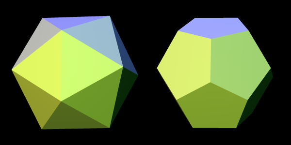
An example of using the TriangleMesh class is provided in icosahedron.cpp: the class Icosahedron derives from class TriangleMesh, and its constructor shows how to call AddPoint and AddTriangle to build a 20-sided regular polyhedron. When you run the raytrace unit test, an icosahedron (and a dodecahedron) will appear in the output file polyhedra.png, thanks to the function TestPolyhedra in main.cpp. (See Figure 12.5.)
| |
|
Writing code for a complex solid with many triangular faces, as we see in the Icosahedron constructor, can be a bit challenging. I happened to have a paper model of an icosahedron already cut, folded, and glued for use as a reference. I wrote the numbers 0 to 11 on the 12 vertices of my paper model, and the letters "a" through "t" on its 20 faces. Each numbered vertex became a call to AddPoint, and each lettered face became a call to AddTriangle. As I coded each call to AddTriangle, I would be sure to type in its three vertices in a counterclockwise order, so that TriangleMesh::AppendAllIntersections would calculate surface normal vectors correctly pointing outward from the icosahedron's body (instead of inward). It may sound primitive and tedious to build a paper model like this, but I really don't know a better way to visualize the relationships between the vertices and triangular faces for a complicated solid like an icosahedron. I tried to draw diagrams on paper, but kept ending up with confusing messes. With the model in hand, it took just a few minutes to write the Icosahedron constructor, and it worked correctly the first time— no debugging needed! I should also mention that Wikipedia's article on the icosahedron was very helpful in that it explained the exact coordinates for all the vertex points. That made it very easy to code all the calls to AddPoint.
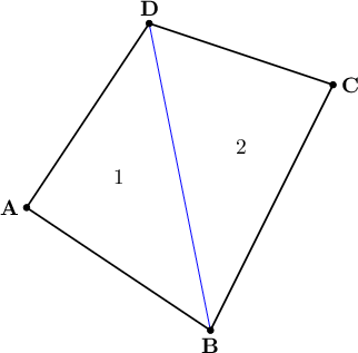
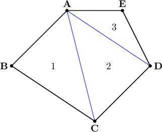
TriangleMesh can be used to build solids that have faces that are polygons other than triangles. Any polygon can be split up into triangles. For example, quadrilaterals and pentagons can be replaced with equivalent triangles as shown in Figures 12.6 and 12.7.
| |
|
| |
|
TriangleMesh provides helper methods for these two cases called AddQuad and AddPentagon. As you can see in imager.h, these inline methods result in multiple calls to AddTriangle. Just like AddTriangle, these methods require the caller to pass the point indices in a counterclockwise order as seen from outside the solid object. It is possible to modify the code to add more helper methods for polygons with even more sides: hexagons, heptagons, etc., if you wish.
You can use TriangleMesh to model all kinds of complicated solid objects using polygonal faces. With some careful planning (perhaps with the help of some paper and glue before programming) you can bring these objects to life and place them in a scene, with realistic three-dimensional lighting and shadows.