Chapter 9: Refraction
9.1 Why refraction before reflection?
Usually I like to explain simpler things before more complicated things, but this is an exception to that rule. Refraction is more complicated than mirror reflection, both mathematically and algorithmically, but I discuss it first because we cannot calculate mirror reflection without calculating refraction first. This is because we don't know how much light reflects from a transparent (or partially transparent) object until we know what portion of light refracts through it. As mentioned briefly before, there are two physical effects that add up to the total mirror reflection: refractive reflection and glossy reflection. A transparent substance causes a ray of light to split into two weaker rays, one that is bent and passes through the substance and another that is reflected from the surface. Once we determine what portion of the light ray is reflected due to refraction, we can combine that with the effects of glossy reflection to calculate total mirror reflection.
9.2 Understanding the physics of refraction
But first we will focus on refraction. When a ray of light passes from one transparent substance into another one, it generally changes its direction, deviating from the straight line path it was on. The amount by which it bends depends on the angle of the ray of light with respect to the surface, along with the optical nature of the two substances involved. Interestingly, the change in direction results because of changes in the speed of light passing through different substances, and the fact that light behaves like waves. Light travels through a vacuum at about $3\times10^8$ meters per second, but it slows down significantly when passing through transparent matter like water or glass.
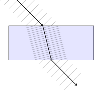
When light passes at an angle from one substance into another that causes it to travel slower, the parts of a given light wave that reach the surface first are slowed down before other parts of the same wave that reach the surface a little later. As seen in Figure 9.1, because different parts of the same wave are slowed down at different times, the direction of the wave is bent. The new direction is closer to being perpendicular to the surface.
To help understand why the speed change causes a direction change, imagine you are pulling a cart in a straight line across a concrete road. Suppose your path wanders off the left side of the road into some soft sand. For the period of time that the left wheels are slowed down by the sand, but the right wheels are still on concrete, the cart would inevitably start to curve more toward the left. If a little later the right wheels enter the sand also and are forced to slow down to the same speed as the left wheels, the cart would then tend to move along a straight path again, but more slowly, and on a different heading than when you started.
The same figure shows how refraction in the opposite direction occurs when the wave emerges from the other side of the substance: the parts of a wave that exit the substance first speed up before other parts, causing the wave to bend away from the surface's perpendicular line.
|
Figure 9.1: Waves of light entering a substance at some angle from the perpendicular. The substance slows down the light waves, causing them to be spaced closer together. The left part of each wave enters the substance before the right part, causing it to slow down first. This forces the entire wave to change direction. The inverse happens when the waves leave the substance. |
|
If $c$ represents the speed of light in a vacuum and $v$ represents the speed of light in a transparent substance, we can use the ratio $N = \frac{c}{v}$ to calculate how much that substance causes light to bend under various circumstances. We will call $N$ the refractive index of the substance. Because the refractive index is the ratio of two speeds, no matter what speed units are used to express them (so long as both speeds are measured using the same units: meters per second, miles per hour, etc.), the units cancel out by division and the refractive index has same dimensionless numeric value. The refractive index $N$ is inversely related to the speed of light $v$ passing through the substance. The more the substance slows down light, the more $v$ gets smaller and therefore the larger $N$ gets. Nothing can make light travel faster than $c$ (at least according to Einstein's theories of relativity), so actual substances in the real world always have $N \ge 1$. Typical values for $N$ are $1.333$ for water and $1.5$ to $1.6$ for common kinds of glass. Toward the lower end of the scale is air at $1.0003$. One of the higher values for refractive index is diamond, having $N = 2.419$. The C++ code that accompanies this book allows a wide range of refractive index values, and the header file imager.h lists several common values for convenience:
    const double REFRACTION_VACUUM   = 1.0000;
    const double REFRACTION_AIR      = 1.0003;
    const double REFRACTION_ICE      = 1.3100;
    const double REFRACTION_WATER    = 1.3330;
    const double REFRACTION_GASOLINE = 1.3980;
    const double REFRACTION_GLASS    = 1.5500;
    const double REFRACTION_SAPPHIRE = 1.7700;
    const double REFRACTION_DIAMOND  = 2.4190;
Wikipedia has a more complete list of refractive indices for the curious reader:
http://en.wikipedia.org/wiki/List_of_refractive_indices
9.3 Snell's Law adapted for vectors
|
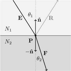
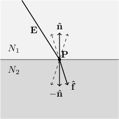
Figure 9.2: Light passing into a substance with a higher refractive index ($N_2 > N_1$) is bent toward a line perpendicular to the surface. The light ray $\mathbf{E}$ passes through the top substance (whose refractive index is $N_1$), strikes the boundary between the two substances at intersection point $\mathbf{P}$, and most of it continues through the bottom substance (whose refractive index is $N_2$) along the direction vector $\mathbf{F}$. A small portion of the light is reflected along $\mathbf{R}$. |
|
|
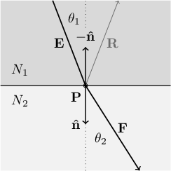
Figure 9.3: Light passing into a substance with a lower refractive index ($N_2 < N_1$) is bent away from a line perpendicular to the surface. As in the previous figure, the light travels from the top along $\mathbf{E}$, strikes the intersection point $\mathbf{P}$, and bends to travel in a new direction $\mathbf{F}$. (As before, a small amount reflects in the direction $\mathbf{R}$). |
|
9.3.1 Introduction to Snell's Law
Figure 9.2 shows how a ray of light bends when it passes from one substance into another having a higher refractive index, and Figure 9.3 shows the inverse case, where a ray of light passes from one substance into another with a lower refractive index. In the first case, the ray is bent to a smaller angle from a line perpendicular to the surface, and in the second case, the ray is bent to a larger angle. Both cases can be treated as mathematically identical, using the following emperical equation known as Snell's Law:
\[
N_1 \sin(\theta_1) = N_2 \sin(\theta_2)
\]
In both figures, $N_1$ is the refractive index of the substance on the top and $N_2$ is that of the bottom substance. Both figures show a light ray $\mathbf{E}$ passing from the top substance into the bottom substance. The light ray strikes the boundary point $\mathbf{P}$ between the two substances at an angle $\theta_1$ from the dotted perpendicular line, and is bent to a new angle $\theta_2$ from the perpendicular, thus traveling along a new direction $\mathbf{F}$.
9.3.2 Refractive reflection
As anyone knows who has looked at a pane of glass or a puddle of clear water, transparent substances form mirror-like images. Physicists determined long ago that reflection and refraction are inseparable. Any substance that refracts light will also reflect it. An interface between transparent substances effectively splits the light energy along two rays, one that reflects back into the substance from which the incident light originated and the other that refracts into the substance on the other side of the interface. The amount of incident light that the surface reflects depends on the angle that the light strikes that surface. There is always some amount of reflection, but the amount increases nonlinearly the more an incident ray slants from a line perpendicular with the surface.
9.3.3 Special case: total internal reflection
|
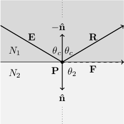
Figure 9.4: A ray of light $\mathbf{E}$ passing into a substance of lower refractive index at the critical angle of incidence $\theta_c$. Snell's Law indicates that refracted ray $\mathbf{F}$ is bent to $\theta_2 = 90°$ from the dotted perpendicular line, meaning it grazes the boundary between the two surfaces. In practice, at the critical angle and beyond, refraction vanishes and all of the light is reflected along the direction $\mathbf{R}$. |
|
When a light ray passes from one substance into another of lower refractive index, for example from water into air, there is a limit to how steep the entry angle $\theta_1$ can be before refraction is no longer possible. When $\theta_1$ increases to a value such that $\theta_2$ reaches $90°$, refraction ceases and all of the light energy is reflected. The value of $\theta_1$ where this occurs is called the critical angle of incidence, which we will designate $\theta_c$. Figure 9.4 shows the same optical setup as 9.3, only with the incident light ray $\mathbf{E}$ at the critical angle $\theta_c$. We can use Snell's Law to calculate $\theta_c$ by replacing $\theta_1$ with $\theta_c$ and setting $\theta_2 = 90°$, which means that $\sin(\theta_2)=1$. Solving for $\theta_c$ gives us:
\[
\theta_c = \arcsin \left( \frac{N_2}{N_1} \right)
\]
The "$\arcsin$" here is the inverse sine, a function that returns the angle whose sine is its argument. Because the sine of an angle must be somewhere between $-1$ and $+1$, the inverse sine is defined only when its argument is between $-1$ and $+1$. If $N_2 > N_1$, the $\arcsin$ argument goes out of bounds, and therefore there is no critical angle $\theta_c$. This is why total reflection can occur only when the light travels into a substance with a lower refractive index.
9.3.4 Setting up the vector equations for refraction
If our task were simply the calculation of the angle $\theta_2$, things would be quite simple. Unfortunately, we are dealing with vectors in three-dimensional space. We know the two refractive indices $N_1$ and $N_2$, the incident light ray vector $\mathbf{E}$, and the surface normal vector $\mathbf{\hat{n}}$ indicating the direction perpendicular to the interface between the two substances. From these known quantities, we need to calculate the direction vector $\mathbf{F}$ of the refracted light ray. To set up the solution, we first define unit vectors that point in the same direction as $\mathbf{E}$ and $\mathbf{F}$:
\[
\mathbf{\hat{e}} = \frac{\mathbf{E}}{\lvert \mathbf{E} \rvert}
\quad \quad \quad \quad
\mathbf{\hat{f}} = \frac{\mathbf{F}}{\lvert \mathbf{F} \rvert}
\]
Using the fact that the dot product of two unit vectors is equal to the cosine of their included angle, in combination with Snell's Law, we can write the following system of equations that indirectly relate the refractive indices $N_1$ and $N_2$ with the unit vectors $\mathbf{\hat{e}}$ and $\mathbf{\hat{f}}$ via the incident angle $\theta_1$ and the refraction angle $\theta_2$.
\[
\begin{cases}
& N_1 \sin(\theta_1) = N_2 \sin(\theta_2) \\
& \mathbf{\hat{e}} \cdot \mathbf{\hat{n}} = \pm \cos(\theta_1) \\
& \mathbf{\hat{f}} \cdot \mathbf{\hat{n}} = \pm \cos(\theta_2)
\end{cases}
\]
9.3.5 Folding the three equations into one
The $\pm$ symbols in the second and third equation result from the ambiguity of the normal vector $\mathbf{\hat{n}}$: a careful consideration reveals that there is no relationship between the ray entering or leaving a particular object and whether the refractive index is increasing or decreasing. The incident ray unit vector $\mathbf{\hat{e}}$ might be going "against" the normal vector $\mathbf{\hat{n}}$ or "with" it, and in either case the light ray may be entering a region of higher or lower refractive index. The two concepts are completely independent. The ambient refractive index may be higher or lower than the refractive index inside the object, the ray may be entering or leaving the object, and furthermore, the ray may be passing into an object that is embedded inside another object.
In mathematical terms, we want to describe the angle $\theta_1$ as the smallest angle between the vector $\mathbf{E}$ (or its unit vector counterpart $\mathbf{\hat{e}}$) and the dotted perpendicular line, whether $\mathbf{\hat{n}}$ is on the same side of the surface as the incident light ray $\mathbf{E}$ (as shown in Figure 9.2) or on the opposite side (as shown in Figure 9.3). In the first case, we would have $\mathbf{\hat{e}} \cdot \mathbf{\hat{n}} = \cos(\theta_1)$, and in the second case $\mathbf{\hat{e}} \cdot (-\mathbf{\hat{n}}) = -\mathbf{\hat{e}} \cdot \mathbf{\hat{n}} = \cos(\theta_1)$. Putting both cases together results in $\mathbf{\hat{e}} \cdot \mathbf{\hat{n}} = \pm \cos(\theta_1)$, as shown in the system of equations above. The same reasoning applies to the $\pm$ that appears in the equation for $\mathbf{\hat{f}}$.
Yet we need to use the normal vector as part of the mathematical solution, because when we find an intersection, it is the only thing available to us that describes the orientation of the boundary between the two substances. There is a happy way to circumvent this problem, however: we square both sides of all three of the preceeding equations, eliminating the both instances of $\pm$.
\[
\begin{cases}
& N_1^2 \sin^2(\theta_1) = N_2^2 \sin^2(\theta_2) \\
& (\mathbf{\hat{e}} \cdot \mathbf{\hat{n}})^2 = \cos^2(\theta_1) \\
& (\mathbf{\hat{f}} \cdot \mathbf{\hat{n}})^2 = \cos^2(\theta_2)
\end{cases}
\]
A quick note on notation: when you see $\sin^2(x)$ or $\cos^2(x)$, it means the same thing as $(\sin(x))^2$ or $(\cos(x))^2$, namely taking the sine or cosine of the angle and multiplying the result by itself.
Squaring the equations also lets us further the solution by use of a trigonometric identity that relates the sine and cosine of any angle $x$:
\[\cos^2(x) + \sin^2(x) = 1\]
We can thus express the squared sines in terms of the squared cosines by rearranging the trig identity as:
\[\sin^2(x) = 1 - \cos^2(x)\]
This lets us replace the squared sine terms in the first equation with squared cosine terms:
\[
\begin{cases}
& N_1^2 \left(1 - \cos^2(\theta_1) \right) = N_2^2 \left(1 - \cos^2(\theta_2) \right) \\
& (\mathbf{\hat{e}} \cdot \mathbf{\hat{n}})^2 = \cos^2(\theta_1) \\
& (\mathbf{\hat{f}} \cdot \mathbf{\hat{n}})^2 = \cos^2(\theta_2)
\end{cases}
\]
By substituting the second and third equations into the first, we completely eliminate the angles and trig functions to obtain a single equation:
\[
N_1^2 \Big(1 - (\mathbf{\hat{e}} \cdot \mathbf{\hat{n}})^2 \Big)
= N_2^2 \Big(1 - (\mathbf{\hat{f}} \cdot \mathbf{\hat{n}})^2 \Big)
\]
9.3.6 Dealing with the double cone
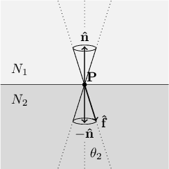
We could solve this equation for the unknown value $(\mathbf{\hat{f}}\cdot\mathbf{\hat{n}})^2$ in terms of the other quantities (which all have known values), but we would still run into a problem: there are an infinite number of unit vectors $\mathbf{\hat{f}}$ whose squared dot product with the normal vector $\mathbf{\hat{n}}$ would yield the known numeric quantity on the other side of the equation. Although $\mathbf{\hat{n}}$ is a known vector, and thus its position is fixed in space, there are an infinite number of unit vectors $\mathbf{\hat{f}}$ whose squared dot product with $\mathbf{\hat{n}}$ will be equal to the value $\cos^2(\theta_2)$. Figure 9.5 shows that the set of all such $\mathbf{\hat{f}}$ sweeps out a pair of cone shapes from the incidence point $\mathbf{P}$, one cone for each side of the surface.
|
Figure 9.5: For specific values of $\mathbf{\hat{n}}$ and $\theta_2$, the set of all $\mathbf{\hat{f}}$ such that $(\mathbf{\hat{f}} \cdot \mathbf{\hat{n}})^2 = \cos^2(\theta_2)$ sweeps out an infinite number of directions from the intersection point $\mathbf{P}$, forming a double-cone shape. We want to solve for the actual refraction vector $\mathbf{\hat{f}}$ as labeled in the figure. |
|
Our original goal was to find the direction vector $\mathbf{F}$ or its unit vector counterpart $\mathbf{\hat{f}}$. (We aren't picky here; any vector pointing in the same direction will be fine, meaning any vector of the form $\mathbf{F} = p\mathbf{\hat{f}}$ where $p$ is a positive scalar.) Clearly we need something extra to further constrain the solution to provide a specific answer for $\mathbf{F}$ itself. Our first clue is that the vectors $\mathbf{E}$, $\mathbf{\hat{n}}$, and $\mathbf{F}$ must all lie in the same plane, because to do otherwise would mean that the ray of light would be bending in an asymmetric way. Imagine yourself inside the top substance looking down at the point $\mathbf{P}$ exactly perpendicular to the boundary. Imagine also that the light ray $\mathbf{E}$ is descending onto the surface from the north. Both of the involved materials are assumed to be completely uniform in composition, so there is no reason to think they would make the ray veer even slightly to the east or west; why would one of those directions be preferred over the other? No, such a ray of light must continue toward the south, perhaps descending at a steeper or shallower angle depending on the refractive indices, but due south nonetheless.
Constraining $\mathbf{F}$ (and therefore $\mathbf{\hat{f}}$) to lie in the same plane as $\mathbf{\hat{n}}$ and $\mathbf{E}$ leads to a finite solution set for $\mathbf{\hat{f}}$. The double cone intersects with this plane such that there are now only four possibile directions for $\mathbf{\hat{f}}$, as shown in Figure 9.6. Only one of these four directions is the correct solution for $\mathbf{\hat{f}}$. The other three are "phantom" solutions that we must eliminate somehow. But we are making progress!
|
Figure 9.6: Requiring $\mathbf{\hat{f}}$ to lie in the same plane as $\mathbf{E}$ and $\mathbf{\hat{n}}$ can be visualized as slicing that common plane through the double cones from the previous figure. This results in a set of four possible solutions for $\mathbf{\hat{f}}$ instead of an infinite set. We still need to figure out how to pick the correct $\mathbf{\hat{f}}$ while discarding the three "phantom" solutions, shown here as dashed vectors. |
|
9.3.7 Constraining $\mathbf{F}$ to the correct plane
But before we get ahead of ourselves, how do we write another equation that mathematically constrains $\mathbf{F}$ to the same plane as $\mathbf{E}$ and $\mathbf{\hat{n}}$ in the first place? The answer is to write $\mathbf{F}$ as a linear combination of the incidence unit vector $\mathbf{\hat{e}}$ and the surface normal unit vector $\mathbf{\hat{n}}$:
\[
\mathbf{F} = \mathbf{\hat{e}} + k \mathbf{\hat{n}}
\]
Here, $k$ is a scalar parameter that determines how far the light ray is bent from its original direction $\mathbf{\hat{e}}$, either toward or away from the normal vector $\mathbf{\hat{n}}$. Depending on the situation, the as yet unknown value of $k$ may be negative, positive, or zero.
Recalling that $\mathbf{\hat{f}} = \frac{\mathbf{F}}{\lvert \mathbf{F} \rvert}$, we can now write $\mathbf{\hat{f}}$ as
\[
\mathbf{\hat{f}} = \frac{\mathbf{\hat{e}} + k \mathbf{\hat{n}}}{\lvert \mathbf{\hat{e}} + k \mathbf{\hat{n}} \rvert}
\]
Now we substitute this rewritten form of $\mathbf{\hat{f}}$ into the earlier equation where we eliminated the squared sines and cosines:
\[
N_1^2 \Big(1 - (\mathbf{\hat{e}} \cdot \mathbf{\hat{n}})^2 \Big)
= N_2^2 \left(1 -
\left(\frac
{\mathbf{\hat{e}} + k \mathbf{\hat{n}}}
{\lvert \mathbf{\hat{e}} + k \mathbf{\hat{n}} \rvert}
\cdot \mathbf{\hat{n}}\right)^2
\right)
\]
9.3.8 Reducing to a scalar equation in $k$
At this point we have a single equation with a single unknown $k$. Solving for $k$ is a little bit of work. We start by expanding the squared dot product term on the right side of the equation. Let's focus on that part alone for a little while. Later we will take the result and plug it back into the previous equation. First we factor out the magnitude term $\lvert \mathbf{\hat{e}} + k \mathbf{\hat{n}} \rvert$ in the denominator. We can do this because it is a scalar.
\[
\left(\frac
{\mathbf{\hat{e}} + k \mathbf{\hat{n}}}
{\lvert \mathbf{\hat{e}} + k \mathbf{\hat{n}} \rvert}
\cdot \mathbf{\hat{n}}\right)^2
=
\frac
{\left( \left( \mathbf{\hat{e}} + k \mathbf{\hat{n}} \right) \cdot \mathbf{\hat{n}} \right) ^ 2}
{\lvert \mathbf{\hat{e}} + k \mathbf{\hat{n}} \rvert ^ 2}
\]
Now we distribute the dot product in the numerator in a very similar way to distributing a scalar sum multiplied by another scalar in familiar algebra. This is possible because
\begin{align*}
& \left( \mathbf{\hat{e}} + k \mathbf{\hat{n}} \right) \cdot \mathbf{\hat{n}} \\
= & \Big( (e_x,e_y,e_z) + k(n_x,n_y,n_z) \Big) \cdot (n_x,n_y,n_z) \\
= & (e_x + k n_x, e_y + k n_y, e_z + k n_z) \cdot (n_x,n_y,n_z) \\
= & ((e_x + k n_x)n_x, (e_y + k n_y)n_y, (e_z + k n_z)n_z) \\
= & (e_x n_x + k n_x^2, e_y n_y + k n_y^2, e_z n_z + k n_z^2) \\
= & (e_x n_x, e_y n_y, e_z n_z) + k(n_x^2, n_y^2, n_z^2) \\
= & (\mathbf{\hat{e}}\cdot\mathbf{\hat{n}}) + k(\mathbf{\hat{n}} \cdot \mathbf{\hat{n}})
\end{align*}
If you look at the first line and last line of this derivation, it looks just like what you would expect if you were doing algebra with ordinary multiplication instead of vector dot products. We will use this dot product distribution trick again soon, so it is important to understand.
We can simplify the expression further by noting that the dot product of any unit vector by itself is equal to 1. As with any vector, $\mathbf{\hat{n}}\cdot\mathbf{\hat{n}} = \lvert \mathbf{\hat{n}} \rvert^2$, but because $\mathbf{\hat{n}}$ is a unit vector, $\lvert \mathbf{\hat{n}} \rvert^2 = 1$, by definition. Substituting $\mathbf{\hat{n}}\cdot\mathbf{\hat{n}} = 1$, we find that
\[
\left( \mathbf{\hat{e}} + k \mathbf{\hat{n}} \right) \cdot \mathbf{\hat{n}} =
(\mathbf{\hat{e}}\cdot\mathbf{\hat{n}}) + k
\]
Now let's do some work on the squared magnitude term $\lvert \mathbf{\hat{e}} + k \mathbf{\hat{n}} \rvert^2$ we factored out earlier. We take advantage of the fact that the square of any vector's magnitude is the same as the dot product of that vector with itself: for any vector $\mathbf{A}$, we know that $\lvert \mathbf{A} \rvert^2 = \mathbf{A}\cdot\mathbf{A} = A_x^2 + A_y^2 + A_z^2$. Applying this concept to $\lvert \mathbf{\hat{e}} + k \mathbf{\hat{n}} \rvert^2$, and noting again that $\mathbf{\hat{e}}\cdot\mathbf{\hat{e}} = 1$ and $\mathbf{\hat{n}}\cdot\mathbf{\hat{n}} = 1$, we have
\begin{align*}
& \lvert \mathbf{\hat{e}} + k \mathbf{\hat{n}} \rvert^2 \\
= & (\mathbf{\hat{e}} + k \mathbf{\hat{n}}) \cdot \left( \mathbf{\hat{e}} + k \mathbf{\hat{n}} \right) \\
= & (\mathbf{\hat{e}}\cdot\mathbf{\hat{e}}) + 2k(\mathbf{\hat{e}}\cdot\mathbf{\hat{n}}) + k^2(\mathbf{\hat{n}}\cdot\mathbf{\hat{n}}) \\
= & 1 + 2k(\mathbf{\hat{e}}\cdot\mathbf{\hat{n}}) + k^2
\end{align*}
This means the term we were working on becomes
\[
\left(\frac
{\mathbf{\hat{e}} + k \mathbf{\hat{n}}}
{\lvert \mathbf{\hat{e}} + k \mathbf{\hat{n}} \rvert}
\cdot \mathbf{\hat{n}}\right)^2
=
\frac
{\left( (\mathbf{\hat{e}} \cdot \mathbf{\hat{n}}) + k \right)^2}
{1 + 2k(\mathbf{\hat{e}} \cdot \mathbf{\hat{n}}) + k^2}
=
\frac
{(\mathbf{\hat{e}} \cdot \mathbf{\hat{n}})^2 + 2k(\mathbf{\hat{e}} \cdot \mathbf{\hat{n}}) + k^2}
{1 + 2k(\mathbf{\hat{e}} \cdot \mathbf{\hat{n}}) + k^2}
\]
This looks a little intimidating, but things become much more pleasant if you note that since both $\mathbf{\hat{e}}$ and $\mathbf{\hat{n}}$ are known vectors, their dot product is a fixed scalar value. Let's make up a new variable $\alpha$ just to make the math easier to follow:
\[
\alpha = \mathbf{\hat{e}} \cdot \mathbf{\hat{n}}
\]
The previous equation then becomes
\[
\left(\frac
{\mathbf{\hat{e}} + k \mathbf{\hat{n}}}
{\lvert \mathbf{\hat{e}} + k \mathbf{\hat{n}} \rvert}
\cdot \mathbf{\hat{n}}\right)^2
=
\frac
{\alpha^2 + 2 \alpha k + k^2}
{1 + 2 \alpha k + k^2}
\]
We now return to the equation we derived from Snell's Law:
\[
N_1^2 \Big(1 - (\mathbf{\hat{e}} \cdot \mathbf{\hat{n}})^2 \Big)
= N_2^2 \left(1 -
\left(\frac
{\mathbf{\hat{e}} + k \mathbf{\hat{n}}}
{\lvert \mathbf{\hat{e}} + k \mathbf{\hat{n}} \rvert}
\cdot \mathbf{\hat{n}}\right)^2
\right)
\]
Using the $\alpha$ substitution and the algebraic work we just did, this equation transforms into a more managable equation involving only scalars.
\begin{align*}
N_1^2(1 - \alpha^2) & =
N_2^2\left(1 - \frac{\alpha^2 + 2 \alpha k + k^2}{1 + 2 \alpha k + k^2}\right) \\
\\
\left(\frac{N_1}{N_2}\right)^2(1 - \alpha^2) & =
\frac{(1 + 2 \alpha k + k^2)-(\alpha^2 + 2 \alpha k + k^2)}{1 + 2 \alpha k + k^2} \\
\\
\left(\frac{N_1}{N_2}\right)^2(1 - \alpha^2) & =
\frac{1 - \alpha^2}{1 + 2 \alpha k + k^2} \\
\\
1 + 2 \alpha k + k^2 & = \left(\frac{N_2}{N_1}\right)^2
\end{align*}
Desiring to solve for $k$, we write the equation in standard quadratic form:
\[
k^2 + 2 \alpha k + \left(1 - \left(\frac{N_2}{N_1}\right)^2\right) = 0
\]
9.3.9 Picking the correct solution for $k$ and $\mathbf{F}$
The C++ code for CalculateRefraction solves the quadratic equation for $k$ using the helper function SolveQuadraticEquation from algebra.h, just as the Sphere class did for finding intersections with a sphere. As is typical for quadratic equations, there are generally two solutions for $k$. Only one of the two values of $k$ yields a correct value of $\mathbf{F} = \mathbf{\hat{e}} + k \mathbf{\hat{n}}$, while the other produces one of the phantom vectors as depicted in Figure 9.6.
The C++ code figures out which value of $\mathbf{F}$ is correct by determining which one is most aligned with the incident ray $\mathbf{E}$. As you can see in Figure 9.6, the correct value of $\mathbf{F}$ causes the path of the light ray to bend less than any of the three phantom vectors. This means that the correct value of $k$ leads to a value of $\mathbf{E}\cdot\mathbf{F}$ greater than for the phantom vector produced by using the incorrect $k$ value. The code tries both values of $k$, calculates $\mathbf{F} = \mathbf{\hat{e}} + k \mathbf{\hat{n}}$ for both values, and picks the $k$ that maximizes the dot product $\mathbf{E}\cdot\mathbf{F}$. Once the correct value of $\mathbf{F}$ is found, it tells us which way a refracted ray of light travels after passing through the boundary between the two substances.
9.4 Calculating refractive reflection
Up to this point we have been concentrating on calculating the refracted ray while ignoring the part of the light energy that goes into reflection. The member function CalculateRefraction does not need to figure out the direction vector of the refracted ray $\mathbf{R}$. That will be the job of another member function CalculateReflection, which is the topic of the next chapter. However, CalculateRefraction does need to figure out what scalar portion of the incident light is reflected due to refraction. To fulfill this part of its contract, CalculateRefraction is responsible for assigning a value between 0 and 1 to its output parameter outReflectionFactor. The reflection factor is closer to 0 when the incidence angle is nearly perpendicular to the surface, and increases to 1 when the incidence angle reaches or exceeds the critical angle $\theta_c$.
I will not go into much detail about how to derive the formulas for calculating the reflection factor. I will mention that they are called the Fresnel equations, and the curious reader can find out more about them in the following Wikipedia article.
http://en.wikipedia.org/wiki/Fresnel_equations
The Fresnel equations give separate answers depending on the polarization of the incident light. This C++ code does not model light polarization. Instead, it calculates the reflection factor by averaging the higher and lower extremes predicted by the Fresnel equations. It finds the higher and lower values from two consecutive calls to the helper function PolarizedReflection, and assigns the average of the resulting return values to the output parameter outReflectionFactor.
Keep in mind that the complexities of finding the refraction vector and the reflection factor disappear when CalculateRefraction detects that the incident ray experiences total internal reflection. In that case, the function exits early after setting outReflectionFactor to 1, while returning a pure black color value:
    if (sin_a2 <= -1.0 || sin_a2 >= +1.0)
    {
        // Since sin_a2 is outside the bounds -1..+1, then
        // there is no such real angle a2, which in turn
        // means that the ray experiences total internal reflection,
        // so that no refracted ray exists.
        outReflectionFactor = 1.0;      // complete reflection
        return Color(0.0, 0.0, 0.0);    // no refraction at all
    }
9.5 Ambient refractive index
By default, the ray tracing code presented here treats any unoccupied region of space as having a vacuum's refractive index (exactly 1.0), but it is possible to override this default to create images that simulate other ambient environments, such as an underwater scene. To do this, call Scene::SetAmbientRefraction with the desired refractive index as its argument. Here is an example of the underwater simulation:
    Scene scene;
    scene.SetAmbientRefraction(REFRACTION_WATER);
In such an underwater scene, glass objects would become much more subtle, and spherical bubbles of air would become profoundly refractive, acting as lenses that make everything seen through them look tiny.
9.6 Determining a point's refractive index
A caller of CalculateRefraction must pass it the refractive index for the region of space that the ray of light was traversing before hitting the boundary between the two substances. This is the parameter sourceRefractiveIndex. However, it is the job of CalculateRefraction to figure out what the refractive index is on the other side of the boundary. It does this by extrapolating the line along the direction of the light ray a small distance beyond the intersection point to arrive at a test point. Then it must figure out which SolidObject instance (if any) contains that test point.
We encounter a dilemma if there is more than one solid that contains the test point. There is nothing in the ray tracer code that prevents two or more solids from overlapping. In fact, preventing overlap would be an undesirable limitation. What if we want to depict a jar of water with some glass marbles and air bubbles in it? In real life, the marbles and bubbles would be mutually exclusive with the water: wherever there is glass or air, there is no water. But in the ray tracer code, it is far simpler to define a cylindrical volume of water and then add glass spheres for the marbles and spheres of air for the bubbles that occupy the same region of space as the water. In such a scene, if a particular ray of light is passing through the water and strikes an air bubble, we want the air bubble to have priority over the water for determining the new refractive index.
In this same scene, it is conceivable that we could want to have a tiny drop of water inside one of the air bubbles. Here is a case where there is a small body of water overlapping with a larger body of air and an even larger body of surrounding water! We have three subtances overlapping. How is the code to know which substance controls the refractive index at a given point in space? We can't just say that the lower (or higher) refractive index wins, because it would prevent this scene from looking right. It turns out that any attempt for the code to guess which object is dominant will eventually fail to make the programmer happy in some case. Only the programmer knows the artistic intent of which objects have priority over others, so the programmer must choose somehow.
The ray tracer uses a simple and arbitrary rule to break ties for the ownership of a point in space: whichever instance of SolidObject was added to the scene first has priority. It is up to you to call Scene::AddSolidObject in whatever order makes sense for the image you are trying to create. In the example here, you would add the bubbles and marbles to the scene before adding the cylindrical body of water. If you were to add the water first, you would still be able to see the marbles if they were a different color than the water, but the marbles would not bend rays of light, so they would look like colored regions of water instead of glass.
To find the owner of the test point, CalculateRefraction calls the member function PrimaryContainer, passing the test point as its argument. PrimaryContainer iterates through all of the objects in the scene in the same order they were added to the scene, calling the Contains method on each object in turn. The first object whose Contains method returns true for the test point is declared the owner of that point, and PrimaryContainer returns a pointer to that object. If none of the objects contain the test point, PrimaryContainer returns NULL. Therefore, CalculateReflection must check the returned pointer for being NULL. In that case, it uses the scene's ambient refractive index. If the returned pointer is not NULL, CalculateRefraction calls the containing object's GetRefractiveIndex method to determine the refractive index.
9.7 CalculateRefraction source code
Here is the complete code for CalculateRefraction, followed by the helper functions PolarizedReflection and PrimaryContainer.
Color Scene::CalculateRefraction(
    const Intersection& intersection,
    const Vector& direction,
    double sourceRefractiveIndex,
    Color rayIntensity,
    int recursionDepth,
    double& outReflectionFactor) const
{
    // Convert direction to a unit vector so that
    // relation between angle and dot product is simpler.
    const Vector dirUnit = direction.UnitVector();

    double cos_a1 = DotProduct(dirUnit, intersection.surfaceNormal);
    double sin_a1;
    if (cos_a1 <= -1.0)
    {
        if (cos_a1 < -1.0001)
        {
            throw ImagerException("Dot product too small.");
        }
        // The incident ray points in exactly the opposite
        // direction as the normal vector, so the ray
        // is entering the solid exactly perpendicular
        // to the surface at the intersection point.
        cos_a1 = -1.0;  // clamp to lower limit
        sin_a1 =  0.0;
    }
    else if (cos_a1 >= +1.0)
    {
        if (cos_a1 > +1.0001)
        {
            throw ImagerException("Dot product too large.");
        }
        // The incident ray points in exactly the same
        // direction as the normal vector, so the ray
        // is exiting the solid exactly perpendicular
        // to the surface at the intersection point.
        cos_a1 = +1.0;  // clamp to upper limit
        sin_a1 =  0.0;
    }
    else
    {
        // The ray is entering/exiting the solid at some
        // positive angle with respect to the normal vector.
        // We need to calculate the sine of that angle
        // using the trig identity cos^2 + sin^2 = 1.
        // The angle between any two vectors is always between
        // 0 and PI, so the sine of such an angle is never negative.
        sin_a1 = sqrt(1.0 - cos_a1*cos_a1);
    }

    // The parameter sourceRefractiveIndex passed to this function
    // tells us the refractive index of the medium the light ray
    // was passing through before striking this intersection.
    // We need to figure out what the target refractive index is,
    // i.e., the refractive index of whatever substance the ray
    // is about to pass into.  We determine this by pretending that
    // the ray continues traveling in the same direction a tiny
    // amount beyond the intersection point, then asking which
    // solid object (if any) contains that test point.
    // Ties are broken by insertion order: whichever solid was
    // inserted into the scene first that contains a point is
    // considered the winner.  If a solid is found, its refractive
    // index is used as the target refractive index; otherwise,
    // we use the scene's ambient refraction, which defaults to
    // vacuum (but that can be overridden by a call to
    // Scene::SetAmbientRefraction).

    const double SMALL_SHIFT = 0.001;
    const Vector testPoint = intersection.point + SMALL_SHIFT*dirUnit;
    const SolidObject* container = PrimaryContainer(testPoint);
    const double targetRefractiveIndex =
        (container != NULL) ?
        container->GetRefractiveIndex() :
        ambientRefraction;

    const double ratio = sourceRefractiveIndex / targetRefractiveIndex;

    // Snell's Law: the sine of the refracted ray's angle
    // with the normal is obtained by multiplying the
    // ratio of refractive indices by the sine of the
    // incident ray's angle with the normal.
    const double sin_a2 = ratio * sin_a1;

    if (sin_a2 <= -1.0 || sin_a2 >= +1.0)
    {
        // Since sin_a2 is outside the bounds -1..+1, then
        // there is no such real angle a2, which in turn
        // means that the ray experiences total internal reflection,
        // so that no refracted ray exists.
        outReflectionFactor = 1.0;      // complete reflection
        return Color(0.0, 0.0, 0.0);    // no refraction at all
    }

    // Getting here means there is at least a little bit of
    // refracted light in addition to reflected light.
    // Determine the direction of the refracted light.
    // We solve a quadratic equation to help us calculate
    // the vector direction of the refracted ray.

    double k[2];
    const int numSolutions = Algebra::SolveQuadraticEquation(
        1.0,
        2.0 * cos_a1,
        1.0 - 1.0/(ratio*ratio),
        k);

    // There are generally 2 solutions for k, but only
    // one of them is correct.  The right answer is the
    // value of k that causes the light ray to bend the
    // smallest angle when comparing the direction of the
    // refracted ray to the incident ray.  This is the
    // same as finding the hypothetical refracted ray
    // with the largest positive dot product.
    // In real refraction, the ray is always bent by less
    // than 90 degrees, so all valid dot products are
    // positive numbers.
    double maxAlignment = -0.0001;  // any negative number works as a flag
    Vector refractDir;
    for (int i=0; i < numSolutions; ++i)
    {
        Vector refractAttempt = dirUnit + k[i]*intersection.surfaceNormal;
        double alignment = DotProduct(dirUnit, refractAttempt);
        if (alignment > maxAlignment)
        {
            maxAlignment = alignment;
            refractDir = refractAttempt;
        }
    }

    if (maxAlignment <= 0.0)
    {
        // Getting here means there is something wrong with the math.
        // Either there were no solutions to the quadratic equation,
        // or all solutions caused the refracted ray to bend 90 degrees
        // or more, which is not possible.
        throw ImagerException("Refraction failure.");
    }

    // Determine the cosine of the exit angle.
    double cos_a2 = sqrt(1.0 - sin_a2*sin_a2);
    if (cos_a1 < 0.0)
    {
        // Tricky bit: the polarity of cos_a2 must
        // match that of cos_a1.
        cos_a2 = -cos_a2;
    }

    // Determine what fraction of the light is
    // reflected at the interface.  The caller
    // needs to know this for calculating total
    // reflection, so it is saved in an output parameter.

    // We assume uniform polarization of light,
    // and therefore average the contributions of s-polarized
    // and p-polarized light.
    const double Rs = PolarizedReflection(
        sourceRefractiveIndex,
        targetRefractiveIndex,
        cos_a1,
        cos_a2);

    const double Rp = PolarizedReflection(
        sourceRefractiveIndex,
        targetRefractiveIndex,
        cos_a2,
        cos_a1);

    outReflectionFactor = (Rs + Rp) / 2.0;

    // Whatever fraction of the light is NOT reflected
    // goes into refraction.  The incoming ray intensity
    // is thus diminished by this fraction.
    const Color nextRayIntensity =
        (1.0 - outReflectionFactor) * rayIntensity;

    // Follow the ray in the new direction from the intersection point.
    return TraceRay(
        intersection.point,
        refractDir,
        targetRefractiveIndex,
        nextRayIntensity,
        recursionDepth);
}

double Scene::PolarizedReflection(
    double n1,              // source material's index of refraction
    double n2,              // target material's index of refraction
    double cos_a1,          // incident or outgoing ray angle cosine
    double cos_a2) const    // outgoing or incident ray angle cosine
{
    const double left  = n1 * cos_a1;
    const double right = n2 * cos_a2;
    double numer = left - right;
    double denom = left + right;
    denom *= denom;     // square the denominator
    if (denom < EPSILON)
    {
        // Assume complete reflection.
        return 1.0;
    }
    double reflection = (numer*numer) / denom;
    if (reflection > 1.0)
    {
        // Clamp to actual upper limit.
        return 1.0;
    }
    return reflection;
}

const SolidObject* Scene::PrimaryContainer(const Vector& point) const
{
    SolidObjectList::const_iterator iter = solidObjectList.begin();
    SolidObjectList::const_iterator end  = solidObjectList.end();
    for (; iter != end; ++iter)
    {
        const SolidObject* solid = *iter;
        if (solid->Contains(point))
        {
            return solid;
        }
    }

    return NULL;
}
Copyright © 2013 by
Don Cross.
All Rights Reserved.